1. Introduction
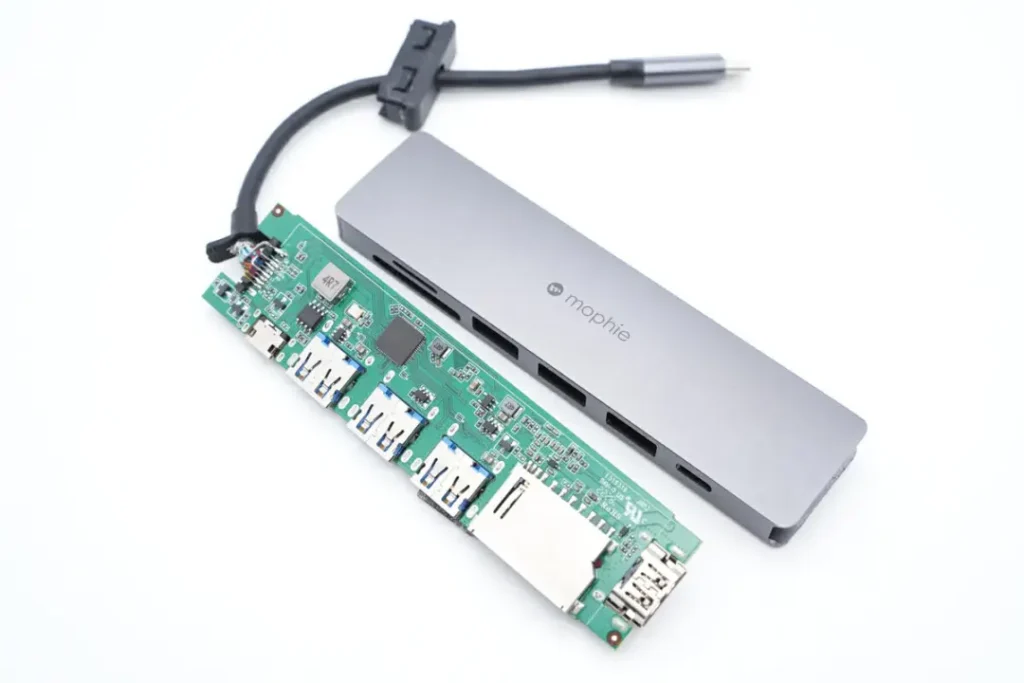
USB-C HUB teardown articles are valuable for understanding the USB-C HUB internal layout, PCB design, and common parts list across mainstream hubs. In this post, we offer a detailed look inside the device—revealing its materials, structure, and thermal pathways. Whether you’re exploring how to teardown a USB-C HUB safely or want to know what’s inside a USB-C HUB, this teardown delivers engineering insight and practical evaluation.
2. Disassembly Steps
USB-C HUB teardown step by step: Discover how to deconstruct and understand the teardown process of a mophie USB-C HUB.
- Remove rubber feet and screws – usually concealed under pads.
- Split the plastic or aluminum shell – use a thin pry tool along seams.
- Extract the PCB assembly – observe solder joints and connector reinforcement.
- Disconnect cable from PCB – carefully De‑solder or unplug to avoid trace damage.
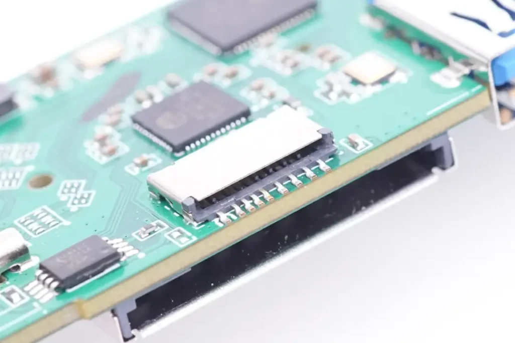
- Identify modular components – HDMI chip, USB 3.x hub IC, PD controller, Ethernet PHY, filters.
3. Internal Structure Analysis
- PCB Layout: Dense but orderly. High-speed different pairs (HDMI, USB‑A, USB‑C) are matched for impedance, but trace spacing is tight—risking crosstalk.
- Power Delivery Section: Discrete MOSFETs with thermal vias. Some models include a tiny heat spreader, but plastic casings limit efficiency, crucial during a teardown of USB-C HUB.
- HDMI & USB ICs: Mounted close to output port. Their proximity increases EMI potential if shielding is missing.
- RJ45 PHY & Magnetics: On smaller hub boards, isolation may be not enough, risking noise transfer into USB rails.
- Card Reader Slot: Soldered directly onto main PCB, convenient, but vulnerable to mechanical stress.
4. Material & Component Overview
| Component | Observations |
|---|---|
| Shell Material | Plastic hubs rely on internal heat sinks; aluminum ones disperse heat more effectively. |
| Connectors | USB‑C often has two through-hole anchor points; cable strain relief is minimal. |
| PCB Quality | Multi-layer board; via-in-pad used, but possibly lacking underfill. These aspects of PCB design are crucial in a USB-C HUB teardown. |
| IC Quality | Standard-brand hub ICs (GenesysLogic, Realtek); PD controllers from lesser-known Chinese OEMs. |
| Passive Components | Ceramic capacitors and small inductors; EMI ferrite beads present but sometimes undersized. |
| Thermal Features | Few hubs include dedicated thermal copper or graphite pads—usually limited by casing design. |
5. Engineering Highlights & Weaknesses
✅ Positives:
- Compact and modular layout keeps components close to ports for short trace length, which is important when considering USB-C HUB teardown analysis.
- PD power section uses MOSFET arrays and thermal vias.
- Aluminum cases often connected to ground, helping EMI suppression.
⚠️ Weaknesses:
- Tight spacing increases heat and EMI risk, especially in plastic shells without partitions.
- USB‑C connector anchoring is often insufficient—leading to failures under frequent plug/unplug cycles.
- PD and hub ICs run close to each other—thermal interaction may cause throttling.
- Minimal strain relief means cable flexing transmits force to solder joints.
6. Potential Improvements
- Redesign mechanical layout to add port spacing and improve thermal airflow to enhance results in future USB-C HUB teardowns.
- Use underfill for USB‑C connector solder joints to increase durability.
- Include internal EMI shields over high-speed IC clusters.
- Upgrade housing material or add heat spreader to manage heat from PD and hub chips.
- Improve cable strain relief using molded grommet or anchored clamp.
- Standardize quality parts (e.g., PD controllers from reputable brands) for longevity.
7. Conclusion & Technical Takeaways
Our USB‑C HUB internal components teardown reveals both smart engineering decisions and common budget compromises. While power and signal routing are optimized for compactness, thermal and mechanical resilience often fall short, all unveiled through a detailed teardown process.
- Robust connector anchoring
- Heat dissipation
- EMI shielding
- Durable cable interface
At WokooDesign, we help OEMs & ODMs take such hubs from good to great—with structural simulations, PCB layout optimization, and manufacturability validation during development.
8. Call to Action
Interested in developing a rugged, high-performance USB‑C HUB? See our case study on accessory engineering and explore more about USB-C HUB teardown by contacting WokooDesign for consultation on ODM projects and product upgrades.
🔗 Related Articles
- USB-C HUB Reviews: Performance, Pros & Design Feedback
In-depth summary of customer experiences and professional advice on USB-C HUBs. - Designing Compact Tech Accessories for Modern Workflows
A look at our design philosophy for productivity-focused hardware. - ODM Guide: How to Develop and Launch Your Own USB-C Hub
Step-by-step OEM/ODM process from idea to mass production.